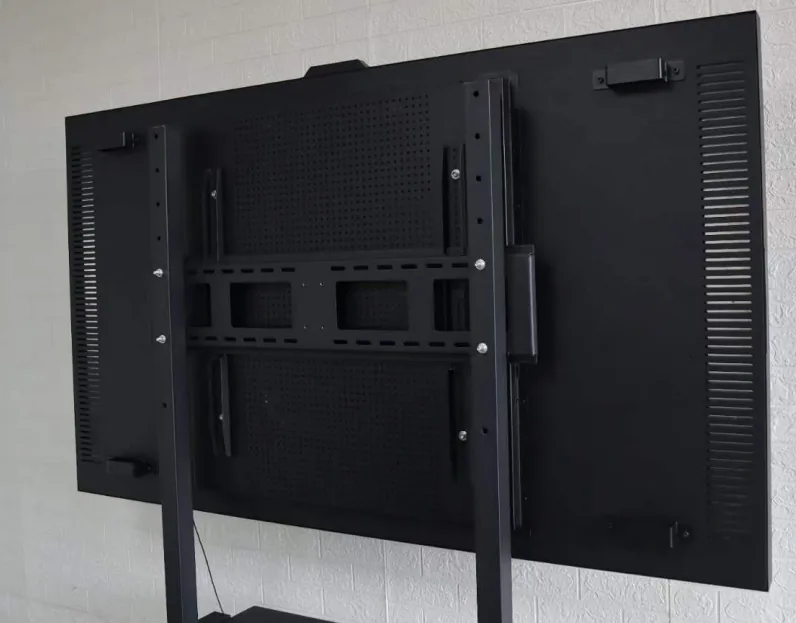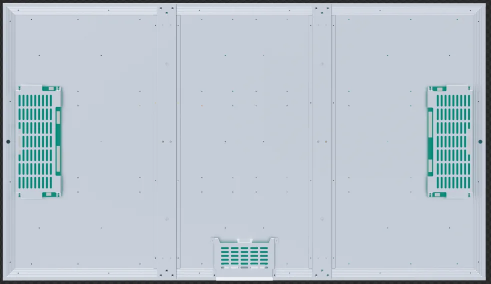
Tender drawings may show the display location but omit base plates, anchors, cable entries, ventilation clearance, lifting access, service doors and division of work between suppliers.
Turn the tender drawing into an interface package
Tender documents often show the display location and visual intent but leave the boundary between equipment, steelwork, foundation, power, data, lifting and commissioning undefined. Those omissions become site changes after manufacturing has already begun.
An interface package makes each connection measurable. It allows the equipment supplier, local contractor and client to approve openings, anchors, cable routes, ventilation and service access before they become expensive to change.
Coordinate structure, foundation and cable entry
Confirm finished dimensions and weight together with base plate, anchor pattern, wall opening or support frame. Identify whether local calculations, wind requirements or engineer approval apply to the supporting structure.
Show power and data entries relative to anchors, drains and doors. A cable route that appears acceptable on elevation can conflict with reinforcement or the equipment base when viewed in section.
Plan lifting, access and work sequence
Record how the unit reaches the final position, including vehicle access, crane or lifting points, temporary storage and protection. Check that doors and removable panels remain usable after surrounding works are complete.
Tie drawing approval and equipment release to site readiness. Shipping early does not protect the programme if the foundation, electrical feed or lifting permit is not available when the unit arrives.
Define acceptance before handover day
Separate factory checks from site checks. Factory acceptance can cover appearance, playback, control, power recovery, aging and documentation; site acceptance can cover installation, weather sealing, network connection and final content.
Assign who supplies test media, network access, lifting labor and local instruments. The acceptance list should identify evidence and sign-off responsibility rather than relying on a general statement that the unit works.
Tender interface responsibility schedule
Add project names and dates to this structure before fabrication starts.
| Interface | Supplier information | Local works | Approval checkpoint |
|---|---|---|---|
| Foundation or wall | Loads, base or opening drawing, service envelope | Civil or structural design and construction | Coordinated drawing before fabrication |
| Power and data | Demand, entry positions and connection requirements | Distribution, protection, conduit and network | Cable-route and isolator review |
| Lifting and installation | Weight, centre of gravity and lifting points | Method, access, permits and equipment | Method statement before shipment |
| Testing and handover | Factory records and equipment checks | Site connections, sealing and commissioning | Signed FAT and SAT lists |
Tender gaps that become site variations
- 01No section drawing
Elevation-only coordination can hide cable, anchor, ventilation and door-clearance conflicts.
- 02Installation responsibility marked by trade name only
Assign deliverables and interfaces, not just labels such as electrical or signage contractor.
- 03Acceptance defined after arrival
The buyer and supplier need a shared test list before the configuration is released.
Questions for the pre-construction meeting
- Who approves the coordinated equipment-interface drawing?
- Are foundation, support and wind requirements owned locally or by the equipment package?
- What access, lifting and storage conditions exist on the planned delivery date?
- Who terminates power, data and weather sealing at the equipment boundary?
- Which documents and functional tests are required for handover?
Who this guide is for
Advertising contractors, transport contractors, signage installers, fit-out companies and project procurement teams.